Electronics, or “I think I broke my multimeter…”
The Electronics lab was a challenge, and there were a couple unanswered questions at the end, but I think I finally understand what all those electrical units of measurement mean.
For Lab 3, I attempted to fly solo. Turns out this was not the best of ideas, as I ended up relying on classmate advice and discoveries many times along the way. (Thanks thanks!)
*note* I realize I have a really crazy Christmas color palette going on with the wires. This is because, turns out, we got the wrong color wire in our kit (green instead of red) and midway through I switched to the school’s supply of red wire.
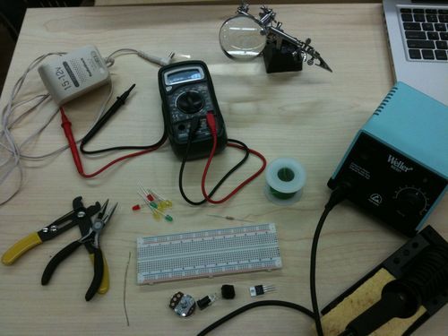
Gathering the ingredients was no problem; I used Google image search to match up the names of some of the components I didn’t recognize with a suggestion of what they’d look like. Here they all are:
Measuring Voltage
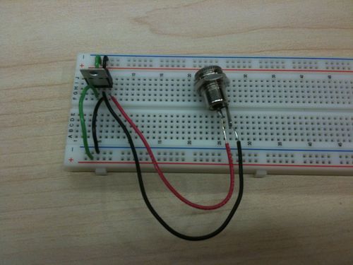
The first step was not a problem; I hooked up the 5V voltage regulator to the breadboard, using short green wires to connect the output pin to the power rail (+) and black wires to connect the ground pin to the ground rail (-).
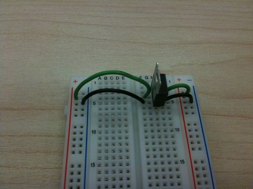
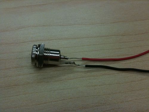
Here’s where things got a little confusing. The power jack included with our kit had three pins. While it was easy to figure out which was the center pin (power), it was unclear which of the other 2 were ground. The pins were all equal length. Finally, a classmate hinted to me that she had found a similar power jack in the tool cabinet with 2 pins rather than 3 (pictured below). I borrowed it for the remainder of the lab.
The next step was to connect the input pin of the voltage regulator to the power source wire of the power jack. This makes sense because the regulator is taking IN whatever voltage it gets from the power source (in this case the wall outlet) and OUTputting 5 volts. The other wire was connected to the ground pin of the regulator, as follows:
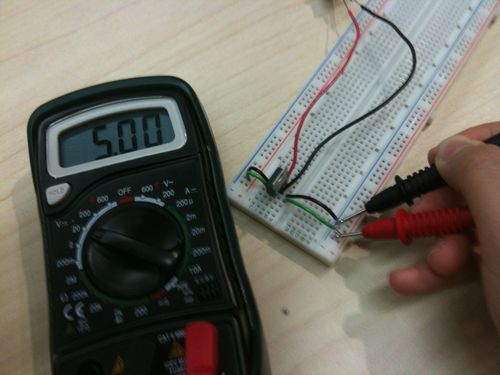
Then I plugged in the power supply (borrowed from another classmate). Testing the voltage yielded a precise 5.00 volts between the output power and the ground. (Testing the voltage BEFORE the voltage regulator yielded 9 volts, which was the setting of the power supply.)
Also, for this step, it was important to remember to set the multimeter to the 0-20V range.
Basic Circuit
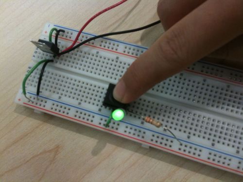
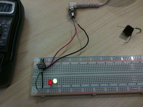
The next portion of the lab requires building a circuit with a single LED as the load and a resistor to “use up” the rest of the electrical energy. A push button was used to complete the circuit.
I connected one of the pins on the button to the power rail, and connected the positive lead of the LED to the other pin on the button. I then connected the LED’s negative lead to one end of the resistor, and the other end went to ground. When the button is pushed, 5 volts of power is supplied to the LED, which then lights up:
Once I brought out the multimeter to measure the voltage, I noticed another oddity in my setup: measuring the voltage across the open switch yields 3.43V, which seems wrong. The voltage across an open switch should be the voltage of the entire circuit—5V. In fact, when I went back to measure the two power and ground wires leading directly out of the regulator, the voltage there had dropped to 3.43V too. I removed the LED, resistor and switch from the circuit and it returned to 5V. After double-checking my circuit against other lab photos, I ascertained that my circuit was correct, but still could not explain the drop in voltage. There was only one thing to do… move on and try to return to this mystery later.
EDIT: Rob the Guru helped me solve the mystery of the missing voltage. Turns out, the LED and resistor together only used part of the power produced by the voltage regulator. That is what I measured – not the total voltage in the entire circuit, but the combined LED and resistor usage.
When the switch is closed, the voltage is 0V. This makes sense because voltage is a measurement of the difference in electrical potential. The closed switch does not use up any electrical energy along the way, so the difference is 0.
The voltage across the LED was 1.95V and the voltage across the resistor was 1.67V. These numbers make sense (if we’re willing to accept the mysterious drop in voltage) because they add up to 3.62, which is roughly the same amount of voltage that is being passed through the switch. All of the electrical energy available in the circuit has been used up by the combined LED and resistor.
Series Circuit
In this next section, I removed the switch, resistor, and LED and replaced it with 2 LEDs in series. What this means is that the electricity flows through one LED and then the other. In my case, it goes first through the red one, then through the green one, and back to ground.
The voltage across the red LED was 2.43V. The voltage across the green LED was 2.29V. The circuit had mysteriously returned to carrying a total of ~5V (or 4.72V to be exact). There is no need for a resistor in this case because the 2nd LED acts as a resistor, dissipating the rest of the electrical energy in the form of light.
Parallel Circuit & Measuring Current
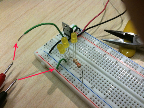
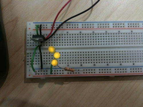
For this section, I cleared the breadboard of LEDs and added 3 yellow ones in parallel. This means all three of their positive leads were hooked up to the power rail (via a wire) and all three of their negative leads went to ground (via a resistor, to avoid burnout). The electricity runs through all three of them simultaneously. The voltage across each LED was 1.8V – the same for all three.
I had some trouble with measuring the current. This was when I had occasion to wonder about my multimeter’s state of health.
To measure the amperage (current), I had to put the multimeter in series with the circuit. To do this, I pulled out one of the power wires, as pictured below and placed the positive probe against the pulled-out wire. I touched the other probe to the other wire “downstream” from this one. This seemed correct except… my multimeter read 0.
EDIT: After consulting Rob the Guru once more, we took apart our multimeter and turns out, the fuse was blown. That would account for the lack of amperage readings.
Afterward, I tried all the unit settings on the DC amperage side of the multimeter dial to no avail; all returned 0. Then I tried placing the multimeter in various other parts of the circuit; still nothing. I finally tried it with a classmate’s multimeter and got 6.14mA. This seemed a little low, but it’s better than nothing.
I noticed that when I used my multimeter to complete the circuit, the LEDs did not light up. But when I used my classmate’s, the LEDs lit up and there was a reading. Another mystery.
Varying Voltage
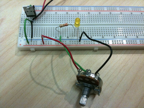
After the tribulations of measuring current, this section was relatively breezy. I wired up the potentiometer as shown below, twisted the kob, and read off some voltages with my multimeter.
The potentiometer’s output varied in voltage, so it worked essentially like a dimmer switch. The LED got brighter and dimmer as I twisted the knob.
At around 2.1V the light becomes visibly lit.
3.43V is the maximum voltage, and 0 is the minimum.